Introduction to 2-Wire and 3-Wire Time Switches
When discussing 2-wire or 3-wire time switches, it primarily concerns the Master unit within the Illuminated range. Below is a breakdown of how these systems function, their components, and essential considerations for installation.
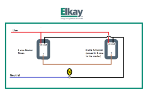
On a 2 wire Master this has a live and switch live connection only and a trigger line for using withd activators. These are perfect for lighting and for retro-fitting or where there is no possibility of getting a neutral to the switch position. They must also utilise a three core connection between the Master and Activator units to work effectively. A common mistake is for people to think that they can connect the whole system via 2 wires only without realising that three cores must run between the Master and Activator switches.
Exceptions for Push-Button Timers
As with all rules there is an exception and it is worth noting that it is possible to work the Push button timers with only two cores between Master and Activator but the installer will have to sacrifice the blue LED locator ring at the activator positions. Illuminated PIR and Touch versions must have a three core connection between Master and Activators.
Understanding the 3-Wire Master
On a 3 wire master there is a live (live in), a switch live (live out) and a neutral connection. There is also a blank terminal which is the trigger line and is for use with the activators. A activator must be connected to a master unit with a three core connection utilising the live, switch live and trigger terminals.The Master unit recieves its own power because it is connected to the mains power and is therefore the easiest to set up. At Elkay we always recommend that where possible the Three wire master is chosen especially if it is possible to get a neutral to the switch position.
Common Issues with 2-Wire Products
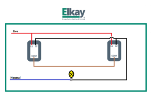
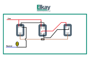
Another issue that crops up with the Illuminated 2 wire products are customers purchasing all two wire Masters and linking them together. This will not work as the Masters will send signals to one another and will keep the load permanently on. Activators are an essential part of the Master and Activator electronic switch set up. See the tables below for the correct part numbers and see the drawings on how to convert from regular on off switches to time switches.
For Two way switching combinations see Table 1 below. For Two way and Intermediate see Table 2 below
Table 1
| Switch Type | Master Unit | Activator Unit |
| Push | 350A-1 | 350A-3 |
| Touch | 360A-1 | 360A-3 |
| PIR | 376A-1 | 376A-3 |
Table 2
| Switch Type | Master Unit | Activator Unit | Activator Unit |
| Push | 350A-1 | 350A-3 | 350A-3 |
| Touch | 360A-1 | 360A-3 | 360A-3 |
| PIR | 376A-1 | 376A-3 | 376A-3 |
Where you have more than 3 switches you simply add another activator switch. See diagrams below showing how to upgrade your switches to energy saving switches using the same wiring.
Finally for those of you that only have two cores between switches see the Tech Tip ‘Want to modernise you Columbus Time lag switches?’ for more details of the solutions from Elkay
If you have any further questions or require more clarification then please contact Elkay Technical on 02890 616505.


